I mentioned earlier that I would go into some detail on machining, and since I’m right in the middle of it right now, seems like a good time to do that.
CNC (Computer Numerical Control) machining is often misunderstood. From the name, you’d think you just push the button and the computer magically does everything for you. But just like CFD earlier, CNC is another area that is just as much an art as it is technology, and the result is only as good as the skill of the person doing it.
There are two main challenges – one is figuring out which tools to use, the types of toolpaths, their sequence, feeds and speeds. The other is holding the part precisely and securely for each operation. Sometimes making custom fixtures is necessary. I try to avoid that as much as possible (and design parts accordingly, to the extent practical). When I do have to make fixtures I design them so that many parts and/or operations can be done in the same tooling. The upside is that once everything is designed, programmed and set up, yes you can just push a button and let it run.
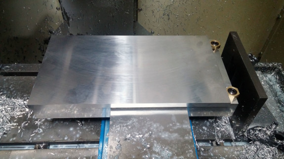
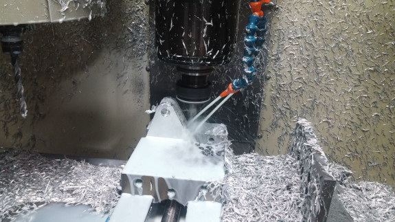
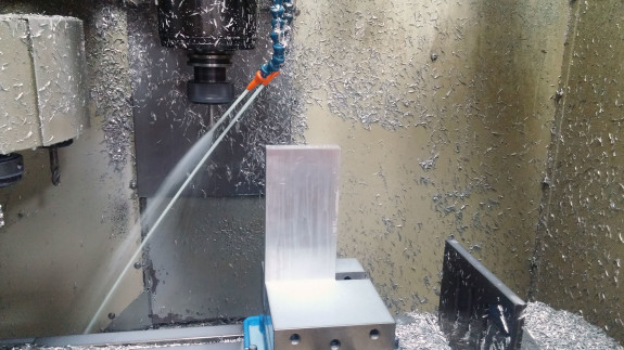
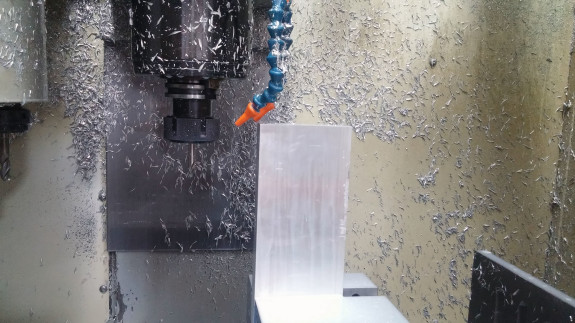
The machine we have is a 3-axis HAAS Mini-Mill. It’s the smallest mill HAAS makes. This actually has some advantages – it’s relatively easy to transport, doesn’t take a lot of space, and is easy to set up. Bigger machines require precision leveling because even the slightest amount of flex over a large span can cause errors or even binding up. This one, close is close enough. Of course there are downsides too, the main one being the size of the part that can be machined, and also speed with which it can be done. We’ve not yet run into anything we couldn’t do in the six years we’ve had it, but we’ve certainly pushed the edges of the envelope. This batch of parts is pushing it the farthest yet.
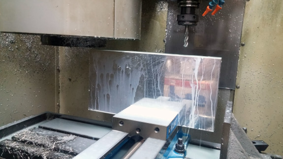
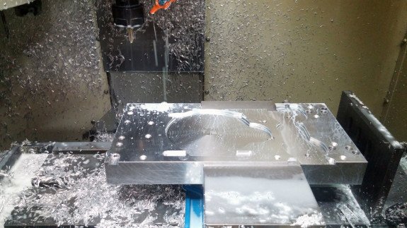
The picture above is a good illustration. It shows the tooling plate being machined – we had to remove all the tools from the tool holder to make sure nothing hits. It’s got 0.2″ clearance. Not bad actually.
First, a bit of background. When I first became a machinist it was out of necessity – we lost our best vendors in the downturn, then as things came back the prices tripled and leadtimes went through the roof. We were looking at $20K in machining and 9 week leadtime. I bought the machine for $18K, material for $2K and two weeks later we were all set. Never looked back.
Early on we got some coaching from experienced machinists. It was extremely helpful, but immediately I wondered about some of the procedures. Then I realized – they make perfect sense for a production machine shop. They run big jobs, on many different machines, and need to be able to put any employee on any job. Customer pays for setup. Our situation is very different. We run small batches, sometimes only one or two parts. We are usually in a huge hurry. Also, setup is inherently error prone so we want to minimize it.
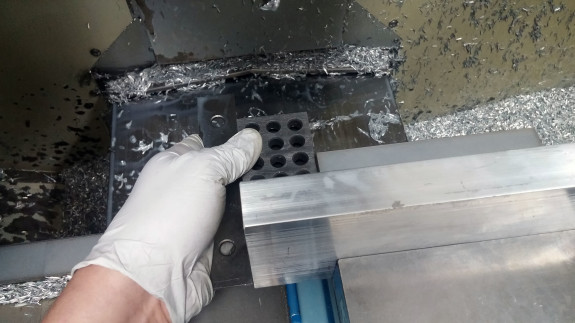
So I came up with a set of procedures that basically centers around the vise. It’s always in the same spot, perfectly aligned, and everything is referenced to that. It does give up some precious Z travel, but the benefits are more than worth it. By the way when I tell machinists how we run things they roll their eyes and say ‘that would last about an hour in our shop’. Very true. Horses for courses.
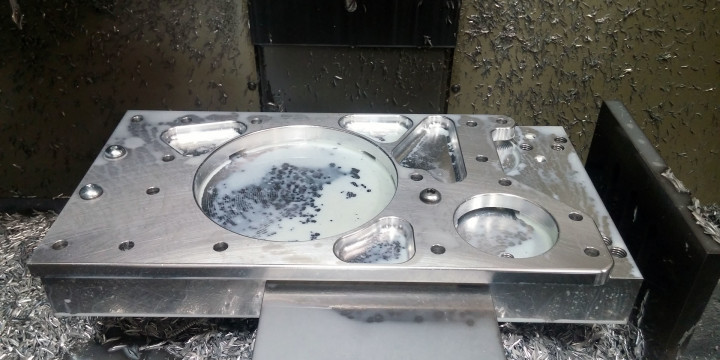
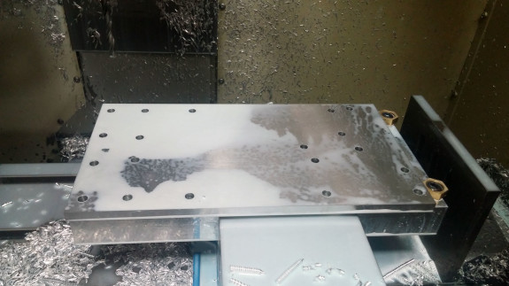
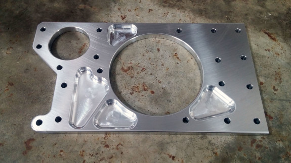
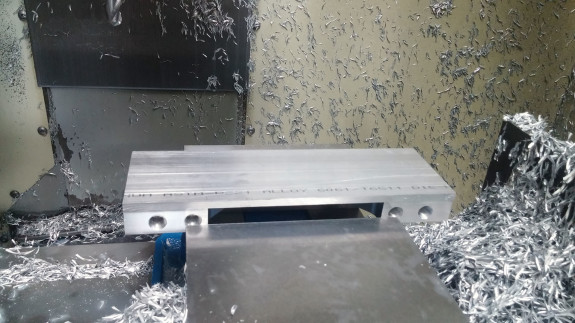
The parts in question are plates for the suspension boxes of the D1PPS. Most machine shops would do this by taking out the vise, bolting a tooling plate to the mill bed, and working with that. If at all possible, I want a tooling plate that fits IN the vise. And, lo and behold, it does. Barely – as I mentioned in the previous post, I have about 0.0018″ room to spare.
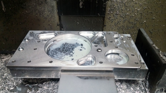
As I’m running the parts, an emergency request comes in from a customer for a modified part. No problem. I pop the tooling plate out of the vise, run the new part, then get back to it. All with no changes in setup whatsoever.

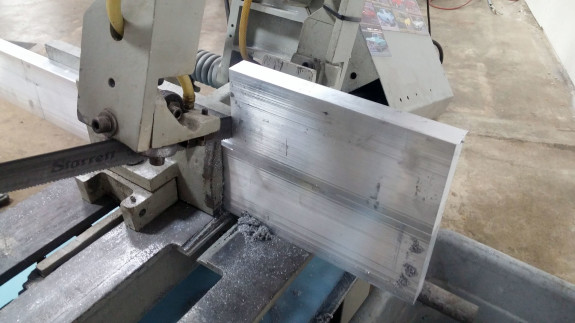
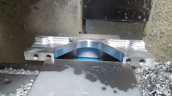
The suspension boxes have lots of pieces to them and some of the smaller parts are no less challenging. Take the cross-braces. They’re 9.10″ wide and have tapped holes on three sides. All of the dimensions need to be accurate to 0.001″ in order for the assembly to work properly. So I have to figure out how to set up and hold the part in every orientation, and maintain the precision. I also want to minimize or eliminate fixturing as much as possible (managed the latter on this one).
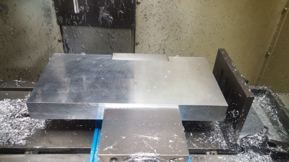
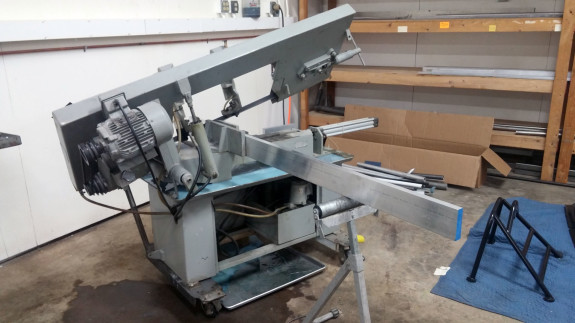
The part starts as raw extruded bar, cut on a saw. It’s not super precise so some extra material is necessary. After the first piece is cut it’s used as a template of sorts for the rest to make things go quicker.
Drilling and tapping the sides of this part really pushes the Z of the machine so accommodations have to be made. Short drill bit, for example.
Another challenge is that the machine’s tool change height is well below the part. So I have to create dummy operations off the part for clearance.
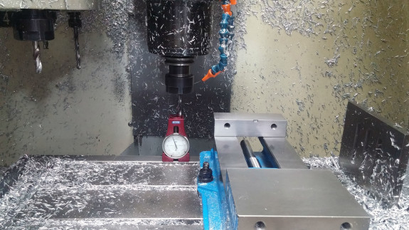
Since everything is referenced off the vise, I try to set it up so that aligning the parts in the vise can be done with parallels and/or 1-2-3 blocks. When done with care, it’s very precise – holding 0.001″ tolerance between ops is not a problem.
This particular part has 6 operations. In a regular machine shop, each op would take half hour or more to set up. Not a problem when running a few hundred parts. Big problem when you are running one or even a dozen. Here, you just do it.
Stuff is moving along. Next post will be all about the engine, quite a few challenges there too.